In functional safety engineering, achieving architectural robustness frequently relies on the implementation of hardware redundancy. However, the integrity of a redundant system can be completely compromised by a Common Cause Failure (CCF). A Common Cause Failure is defined as the simultaneous or sequential failure of multiple independent channels, components, or subsystems resulting from a singular shared event, root cause, or systemic vulnerability.
Overlooking CCFs during system design leads to a severe underestimation of total system risk. When a CCF occurs, it functions as an unmitigated single point of failure (SPF) that completely bypasses parallel safety paths, causing high-integrity systems to fail catastrophically.
Root Sources and Triggers of Common Cause Failures
CCFs are systemic vulnerabilities that typically slip through standard hardware reliability models because they bypass random component wear-and-tear assumptions. They generally originate from five primary engineering and environmental domains:
Design Flaws in Redundancy Architecture:
Introducing shared upstream or downstream dependencies within a redundant layout creates hidden single points of failure. For example, deploying multiple backup generators in a critical data center provides excellent hardware redundancy, but routing all power lines through a single master circuit breaker introduces a catastrophic CCF vector if that specific breaker trips.
Identical Component Homogeneity:
Utilizing identical make, model, or manufacturing batches across multiple redundant subsystems introduces shared hardware vulnerabilities. If an internal silicon defect or component batch error exists within a specific Electronic Control Unit (ECU), using that exact same ECU for both an automotive engine control loop and a transmission safety loop means a single operational condition can disable both systems simultaneously.
Systemic Software and Algorithmic Bugs:
Software faults are inherently systematic rather than random. If redundant microprocessors run identical code blocks, a specific software exception, edge-case math error, or unhandled input variable will cause all processors to crash at the exact same instant, completely neutralizing the software redundancy.
Manufacturing and Assembly Deviations:
Variances introduced during the production or installation phases can embed hidden structural weak points across identical parts. If an assembly facility incorrectly calibrates the torque tools used to secure critical internal connections across a product run, all units within that batch share a high probability of mechanical failure under identical stress profiles.
Environmental Stress Factors:
External operational conditions can exert extreme stress across physically adjacent systems simultaneously. Natural anomalies, such as severe ice storms, high-amplitude seismic events, or localized electromagnetic interference (EMI), can trigger simultaneous, unmitigated failures across parallel power transmission lines or sensory clusters.
The Common Cause Failure Analysis (CCFA) Process
To systematically protect safety-critical architectures from these hidden single-point vulnerabilities, safety engineering teams execute a structured Common Cause Failure Analysis (CCFA).
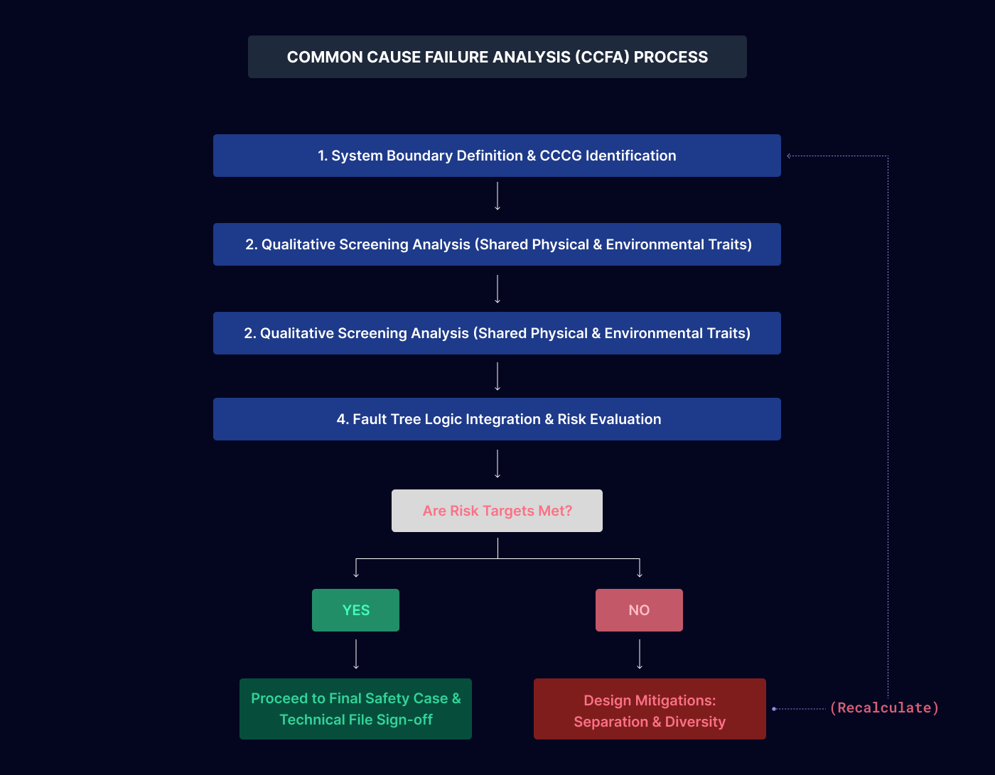
Step 1: System and Interface Boundary Definition
The analysis initiates by explicitly mapping out all physical system boundaries, operational interfaces, and shared support infrastructures (such as shared power distribution networks or cooling lines) to isolate where independent paths interact.
Step 2: Develop the Initial Logic Model
Construct an initial Fault Tree Analysis (FTA) or Reliability Block Diagram (RBD) to map out the logical relationships between components, visually establishing the baseline paths that provide system redundancy.
Step 3: Qualitative Screening Analysis
Engineers systematically screen the logic model to identify components that share common attributes—including identical manufacturer parts, identical software code, adjacent physical locations, or shared power buses—to flag potential CCF vulnerabilities.
Step 4: Detailed Qualitative and Quantitative Estimation
Evaluate the flagged components to deduce the exact mechanisms of failure. Engineers then apply specialized mathematical models to quantify the probability of a concurrent multi-channel failure event.
Step 5: Risk Acceptance Evaluation
The calculated CCF risk profiles are audited against the project's primary Safety Plan and tolerable target metrics to determine if the existing safety margins are acceptable or require further design updates.
Step 6: Recommend Engineering Mitigations
Propose explicit architectural modifications to decouple the common cause pathways. Mitigations generally require implementing physical separation, environmental shielding, or architectural design diversity (such as pairing a micro-electromechanical sensor with an optical sensor).
Step 7: Hazard Tracking and Configuration Monitoring
Log the identified CCF vectors inside the central project hazard log, ensuring that future hardware swaps or software patches undergo rigid impact assessments to prevent re-introducing shared dependencies.
Step 8: Document the Final Safety Case
Compile the analytical findings, logic trees, data assumptions, and validation records into a structured compliance file to provide third-party auditors with clear evidence of systematic risk mitigation.
Overview of Mathematical CCF Estimation Models
Quantifying the impact of common cause events during system validation requires utilizing specialized probabilistic frameworks. Safety software platforms apply five primary mathematical models based on system complexity and data availability:
1. Beta Factor Model
The Beta Factor model is the most widely applied framework in functional safety standards like IEC 61508. It assumes that a fixed, constant fraction (represented by the variable Beta) of the total component failure rate is attributable to common cause events, while the remaining fraction represents independent random hardware failures. While simple to implement, it assumes all components within the redundant cluster fail simultaneously when a CCF triggers, making it less precise for systems with high levels of redundancy (e.g., 2oo4 configurations).
2. Basic Parameter Model
This data-intensive model uses specific parameters to calculate the explicit probability of exact combinations of component failures within a redundant group (e.g., calculating the unique probability that exactly component A and B fail, versus components A, B, and C failing concurrently). This provides an incredibly granular risk assessment, but requires extensive, highly specialized historical field failure libraries that are often unavailable for novel designs.
3. Multiple Greek Letter (MGL) Model
An advanced extension of the Beta Factor model, the MGL framework introduces progressive parameters (such as Beta, Gamma, and Delta) to represent different levels of cascading dependency across a large component group. This allows engineers to calculate a more nuanced probability distribution for partial group failures versus total system collapse, though it increases model complexity and data input demands.
4. Binomial Failure Rate Model
This framework models common cause occurrences as random external "shocks" that hit the system from the environment. Shocks are categorized as either lethal (instantly destroying all components in the group) or non-lethal (where each individual component has a independent probability of surviving the shock). It is highly effective for modeling extreme environmental stressors, but assumes an equal failure probability across all hardware nodes.
5. System Fault Tree Model
This methodology integrates common cause events directly into the system's structural Fault Tree Analysis as explicit, independent basic events connected via logic gates. This produces a highly visual, logically rigorous blueprint of failure propagation paths, though the resulting logic trees can become exceptionally large and complex when evaluating extensive, multi-layered automation facilities.
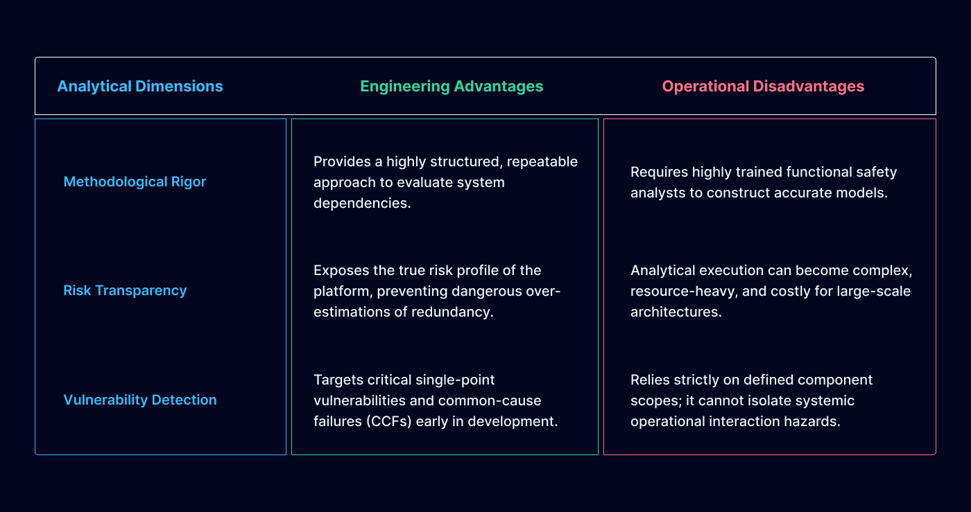
Comparative Evaluation of the CCFA Technique
Traditional Pitfalls in CCF Management
When executing a common cause review, development teams frequently fall into predictable engineering errors that compromise compliance readiness:
Incomplete Variable Investigation:
Restricting the analysis purely to hardware attributes while ignoring the systemic common-cause threats introduced by shared software libraries, identical firmware versions, or human maintenance access profiles.
Overlooking Cascade Interconnections:
Assuming that separate, redundant subsystems are completely isolated when they actually interface with a shared communication bus, common clock line, or centralized internal power regulator node.
Failing to Leverage Visual Logic Modeling:
Relying strictly on flat, text-based spreadsheets instead of building top-down Fault Tree models, which hides complex, multi-layered path dependencies from design reviewers and external auditors.
Ultimately, managing common cause failures is a prerequisite for validating any high-integrity architecture. By applying rigorous Common Cause Failure Analyses early in the product development cycle, matching risks to appropriate mathematical estimation frameworks, and deliberately executing design diversity, engineering organizations can eliminate hidden single-point vulnerabilities and ensure their systems fail safely under all operational conditions.